3 – The quadrature encoder feedback system
So I’ve had to neglect you a little bit and haven’t posted in the last couple of weeks. My apologies for this. It seems the boss is now so interested in our project that he’s insisting that I definitely give him a bit more to work with every week. Between me and you – I reckon he’s building this system. I’m waiting for the day he actually asks me to help him with a problem.
Now, before I carry on, I have to warn you that out of the six months I had to complete this project, 3 of them were spent on getting this feedback system right. It’s complex and has many parts that can go wrong, which is dead against my engineering intuition, but let’s look at why this system was chosen.
What are the options available?
What do we need from a feedback system?
- Direction of movement
- Magnitude of movement
Luckily the Arduino Nano has digital and analogue ports, so there are pretty much no limit to what we can connect. That’s one less worry.
I’m showing you the picture of the printed pan-tilt system again to help you understand how the decision making process worked in my case.
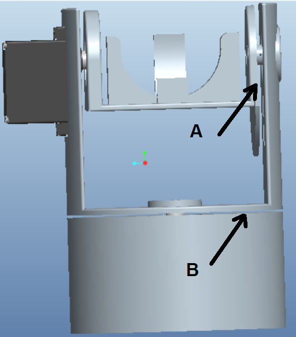
CAD Design of the Pan-Tilt System
By far the easiest and simplest way to provide feedback, in this system, would be to use a potentiometer. It’s very cheap, it’s a simple design and to implement it in the Arduino embedded code would be so simple. The only problem that we have with regards to this solution, is the fact that the potentiometer shaft has to be somehow connected to the shaft that’s feedback is measured. That would be a very complicated solution in the design above where the servo horns are connected directly to the part that they are rotating. The same problem would be present in the sue of a packaged encoder, because the package resembles the shape and function of a potentiometer.
That leaves us with two more options. A reed switch and magnets can be used, but since we want relatively sensitive feedback, we’d need many fine magnets, which can work out expensive.
Of course if money is no object, a sensor perfect for this application can probably be found and implemented, but I am a student on a tight budget. The final option that I’m left with, is the optical sensor. I had a version available to me from our lab’s parts store, but the available sensor would operate over a distance of +- 12mm and that didn’t suit me, because my design would have large gaps in it.
I eventually found the QRE1113 in a breakout board version from Sparkfun. The do an analogue and a digital version, but more on that later.
To enable us to use an optical feedback system, we need a way to inform the sensor that there is movement in the opposing surface. The easiest way to do this, is to apply a pattern of lines to the surface. I found the perfect pattern for this:
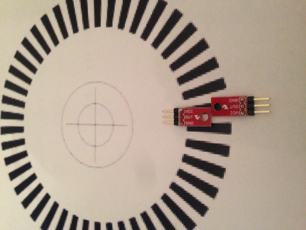
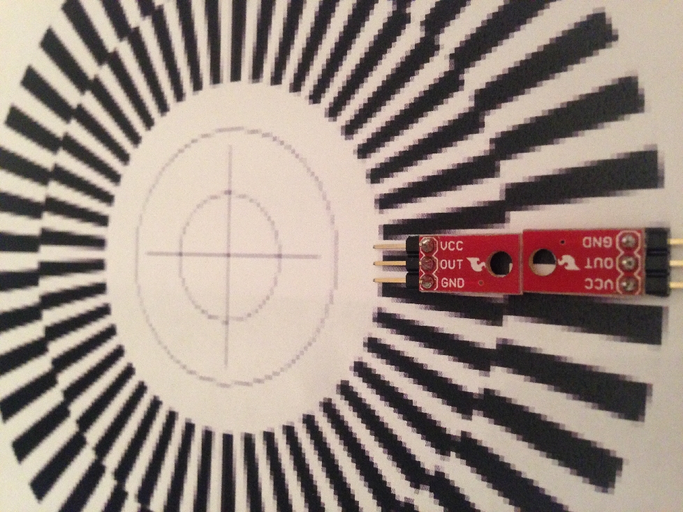
Quadrature pattern
The top pattern would work in that it would indicate movement to the sensor and it is good enough to detect the magnitude of the movement if the sensors are mounted in line. The quadrature pattern shows effectively two patterns, one 90 degrees out of phase with regards to the other. In effect the single pattern can also yield the same result as the out of phase pattern if the sensors are mounted at a calculated offset with regards to one another.
So how does it all work then?
The QRE1113 package consists of an infra red LED and a photo transistor in a single package. The LED shines its light on the pattern on the opposing surface and if the light hits a white area, more light is reflected back, so the transistor is fully saturated and thus on. If the light hits a black area, much less light is reflected, so the transistor is not fully switched on and thus very little current is let through.
In the digital version of this breakout board, this will result in either a 1 or a 0 output. In the analogue version, a varied output voltage is detected. The resulting digital wave form for the out of phase pattern resembles the following sketch:
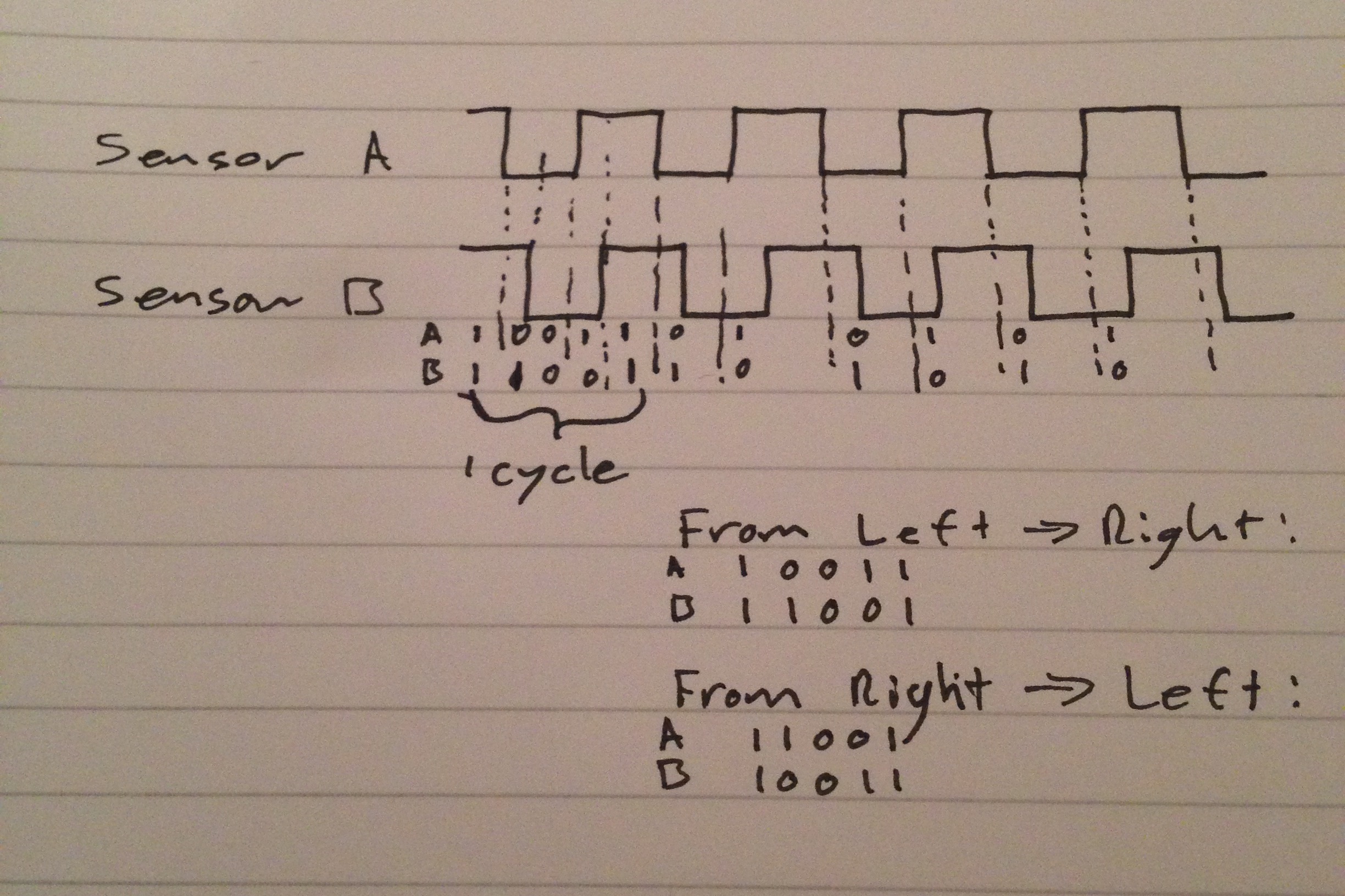
For simplicity, let’s combine the two outputs in one, 2-bit number, say AB. Moving the pattern from left to right gives us a sequence of 11, 01, 00, 10 and then again 11. We have ones and zeros, so let’s assume that this new AB number that we’ve created is a binary number and let’s convert these left to right outputs to something that we understand easily. In the same sequence, we get: 3, 1, 0,2 and then again 3.
If we moved the pattern in the opposite direction, we’d get the sequence 3, 2, 0, 1, 3. So that is the basis of operation for our quadrature encoder.
Now my brain tells me that to keep things simple, I need to use the sensor that gives me a digital output, to achieve this. Right? EH! EEEHHH! If I had one of those big buzzers on Family Fortunes right now, I’d be pressing it, because that’s wrong. I had to learn this the hard way, but luckily you don’t have to. Let’s see why…..
We want the feedback system to always be active, so to speak. This means that we have to implement the system in our embedded code to be active on a hardware interrupt. The ATmega328, which is the micro controller on our Nano board, has several options here. We have two external interrupts called INT1 and INT2. These interrupts can be set to run the interrupt routine on a rising edge, a falling edge or both edges of the incoming digital signal. But we have 4 sensors, two per encoder. We can multiplex them or we can look for another solution. In comes the MC’s Pin Change Interrupts. There are 24 of them, so need for a complex multiplexing setup. We can simply connect every sensor to its own individual pin.
There are a few rules to observe with the interrupt routine, which I shall not go through now. Instead we’ll just look at the relevant rule to our problem. While the MC is running an ISR(Interrupt Service Routine) all other interrupts are disabled. To allow us to use the digital version of the QRE1113, a timer interrupt function is called from one of Arduino’s many libraries. The digital breakout board of the QRE1113 uses a capacitor to give us a digital signal. In Arduino, we need to check how long the capacitor stays charged to establish between low and high input. This requires the use of a delay, which uses in ISR, so if the pattern modes while the program is inside that ISR, no-one will ever know. Hence using a digital sensor is not the best approach.
So what we need to do, is to change our analogue waveform into a square wave or digital signal. There are a few ways to do this, but I decided to use a voltage comparator and specifically the LM339, which is a quad version of what I need. This little device works by supplying it with a reference voltage, if the incoming signal is between 0 and v-ref, the output is zero. If the input is above v-ref, the output will be high. Note the photo below:

Comparator In/Out
From the screen above, you can see the top signal, which is the analogue input signal that is produced by moving the circular pattern. The signal on the bottom of the screen is the converted analogue signal, which is now perfect for use as a digital signal.
The comparator circuit is as follow:
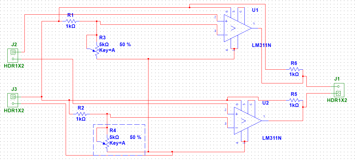
LM339 quad comparator circuit
The circuit above was created for the dual version of the LM339, so please consult the data sheet for correct implementation.
So finally, we need to look at the code that will allow us to use the sensors on interrupt.
First we need to include the right library:
#include <avr/interrupt.h>
Then we need to declare variables for use in the ISR:
/*The volatile variables are used in the interrupt routine*/
volatile int icountX=0, icountY=0; //counts every time a pin goes high or low
volatile int data1 = -1, data2=-1, a=-1, b=-1; //use -1, because -1 does not appear in the data1 added combination
volatile int data3 = -1, data4 = -1, k = -1, l = -1; //for y interrupt
volatile int statusX=0x0, statusY=0x0; //interrupt status
The code that we use in Setup to set the interrupt up:
/* Configure Pin Change Interrupts*/
cli(); // disable global interrupts
PCICR = 0x04; //Set Pin Change Interrupt Control Register for timer 2
// Enable D3,D4,D5, D6 – PCINT19:22
PCMSK2 = 0x78;
PCIFR |=0x00; //reset the interrupt flag
sei(); //enable all interrupts
icountX = 90; //set icount to be the same as the servo “zero” position
icountY = 90;
Finally we need to write the ISR:
ISR(PCINT2_vect)
{
PCIFR |= 0x00; //reset the interrupt flag
data3 = (digitalRead((5)) << 1) + digitalRead(6); //combine the data from the two y sensors
data1 = (digitalRead((3)) << 1) + digitalRead(4); //combine the data from the two x sensors
b = a;
k = l;
a = (data2<<4)+data1; //combine data1 and data2
k = (data3<<4)+data4; //combine data3 and data4
if(a!=b) //if no change occurred on y int pins
{
if(a==0x01 || a==0x13 || a==0x32 || a==0x20)//check if moving Left or right
{ //if moving left, subtract count twice (1 count = 2 degrees)
icountX–;
icountX–;
}
else if(a==0x02 || a==0x23 || a==0x31 || a==0x10)
{ //if moving right, add count twice
icountX++;
icountX++;
}
data2 =data1; //copy data1 into data2
statusX=1; //set the interrupt status to 1 to show that interrupt has occurred
}
if(k!=l)
{
if(k==0x01 || k==0x13 || k==0x32 || k==0x20)//check if moving Left or right
{ //if moving left, subtract count twice (1 count = 2 degrees)
icountY–;
icountY–;
}
else if(k==0x02 || k==0x23 || k==0x31 || k==0x10)
{ //if moving right, add count twice
icountY++;
icountY++;
}
data4 =data3; //copy data1 into data2
statusY=1; //set the interrupt status to 1 to show that interrupt has occurred
}
}
Finally we need to fine-tune the setup to work in the pan-tilt system. When the QRE1113’s datasheet is inspected, it shows that the sensor is at it’s most sensitive to change when it is ~1mm away from the pattern, so for optimum results, it may be helpful to have an oscilloscope at hand.
- Check that the incoming signals for each encoder are out of phase
- Check that the comparator circuit is set up to provide a clean digital output
- Check the sensor output and adjust the distance between sensor and pattern till the highest possible response is detected
- as a tip, it may be helpful to connect a visual feedback as a result of the feedback check, then turn the top part of the system to see if it feeds back correctly
That’s all for now, folks.
We shall crack on next week with the rest of the project. Happy building!